Just a layered sequences example
Other projects

Sometimes I do things just to see them work. This is one of those times.

This testbench uses the layered sequence approach to connect a CPU complex (CPU) to a Sensor Control Unit (SCU). Between those two are an interconnect (XBR) and a Peripherial Control Unit (PCU). The CPU complex speaks AXI to the XBR, the XBR speaks APB to the PCU, the PCU speaks RS-232(ish) to the SCU. Translator sequences replace only the necessary functions in the CPU, XBR, and PCU.

The most recent code is on EDAplayground here:

Big picture block diagrams
The structure of the env
First level translation sequence, PCU to SCU
Second level translation sequence, XBR to PCU
Third level translation sequence, CPU to XBR
Coda


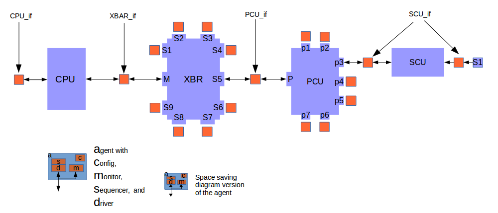
 Below is a block diagram of a simple SoC. Most end-point blocks are not shown since I'm highlighting the path from the CPU complex to the sensor.


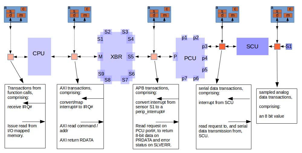
 Here we put in all the interfaces and prepare to do block-level verification.


 On this diagram I've faded out the CPU, XBR, and PCU since the designs are considered to be not developed yet. If we want to test the sensor and SCU with some SW, but we don't want to wait on the completion of the other components, we can make a small test harness with just the SCU. However in this case I'm putting in the framework to allow other parts of the design to be incorporated when they become ready.
 The boxes indicate the type of data that each transaction will have to include and mentions how the data transforms as it passes through the PCU, the XBR, and the CPU.


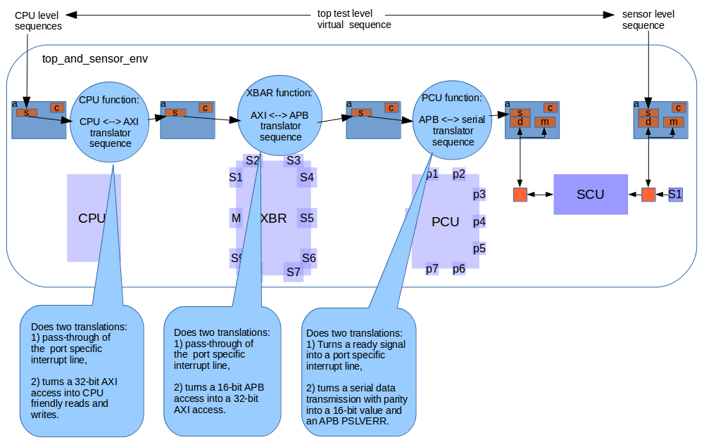
 In the image below the CPU transactions are passed
  • to the cpu_sequencer then through a CPU_XBR translation sequence then
  • to the xbr_sequencer then through an XBR_PCU translator sequence then
  • to the pcu_sequencer then through a PCU_SCU translator sequence and finally
  • to the scu_sequencer which is connected to a driver at the SCU interface.


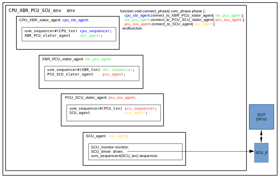
      Here's a diagram of the environment. I like symmetry in names, but in this case it's hard to distinguish one layer from another; so I've color-coded some of the names.
      The only complicated part of layering sequences is layering the sequencers and passing handles of the downstream sequencers to the upstream agent. That's done in the connect phase as shown in the upper right of the diagram below.


      The connect phase uses functions in the agents as shown in the code below. I've put in blue the downstream/upstream connection/use parts for the uppermost layer:
    // -----------------------------------------------
    class CPU_XBR_xlator_agent extends uvm_component#(SCU_txn);
      `uvm_component_utils(CPU_XBR_xlator_agent)
    
      uvm_sequencer#(CPU_txn) cpu_sequencer ;
      XBR_PCU_xlator_agent    xbr_agent ;
    
      function new(string name, uvm_component parent);
        super.new(name, parent);
      endfunction
    
      function void build_phase(uvm_phase phase);
        cpu_sequencer = uvm_sequencer#(CPU_txn)::type_id::create("cpu_sequencer", this);
      endfunction
    
      // connect the agents
      function void connect_to_XBR_PCU_xlator_agent( XBR_PCU_xlator_agent c );
        xbr_agent = c;
      endfunction
    
      virtual task run_phase (uvm_phase phase) ;
        // declare the translator sequences
        CPU_XBR_xlator_irq_seq  xlator_irq_seq ;
        CPU_XBR_xlator_data_seq xlator_data_seq ;
    
        // create  the translator sequences 
        xlator_irq_seq  =  CPU_XBR_xlator_irq_seq::type_id::create("xlator_irq_seq") ;
        xlator_data_seq = CPU_XBR_xlator_data_seq::type_id::create("xlator_data_seq") ;
    
        // connect translation sequences to the upstream sequencers
         xlator_irq_seq.cpu_sequencer = cpu_sequencer ;
        xlator_data_seq.cpu_sequencer = cpu_sequencer ;
    
        // forking start the translation sequences on the downstream sequencer
        fork
           xlator_irq_seq.start(xbr_agent.xbr_sequencer) ;
          xlator_data_seq.start(xbr_agent.xbr_sequencer) ;
        join_none
      endtask
    endclass : CPU_XBR_xlator_agent


     As described in other layered sequence documentation, the core part of layered sequences are the translation sequences. These are:
    1. get_next_item from the upstream sequencer,
    2. create a downstream transaction item,
    3. do a start_item of that on the downstream sequencer,
    4. modify/translate that downstream item according to the information in the upstream transaction,
    5. do a finish_item and when that returns,
    6. modify/translate the upstream item according to the information in the downstream transaction,
    7. issue item_done on the upstream item.

     Even though the connections are ostensibly AXI and APB, in my example testbench I am only including the few parts of those protocols I need for converstion. The translation sequences run in zero time, and the address is not actually a concern. But using the AXI and APB nomenclature provides placeholders for later expansion of the testbench. Here are the core parts of each of the translator sequences.


    PCU_SCU_xlator_data_seq
     The SCU speaks single bit serial data, with parity. The PCU will have to turn that into a limited form of APB. The minimum requirements will be to deserialize and provide a 16-bit data value on PRDATA, and provide an APB slave error code on PSLVERR.
      virtual task body();            The blue color represents the upstream activity, the PCU.
                                      The green color represents the downstream activity, the SCU.
        PCU_txn p_txn; 
        SCU_txn s_txn; 
    
        forever begin
          pcu_token.get(1) ;
          
          pcu_sequencer.get_next_item(p_txn);
          
              s_txn = SCU_txn::type_id::create(.name("s_txn"), .contxt(get_full_name()));
              start_item(s_txn);
    
                  s_txn.go  = ~p_txn.PWRITE ; 
    
              finish_item(s_txn);
          
              p_txn.PRDATA = {7'b0,s_txn.txdata} ;
              parity        = ((s_txn.txdata[0] ^ s_txn.txdata[1]) ^ 
                               (s_txn.txdata[2] ^ s_txn.txdata[3]) ^ 
                               (s_txn.txdata[4] ^ s_txn.txdata[5]) ^  
                               (s_txn.txdata[6] ^ s_txn.txdata[7])) ;
              p_txn.PSLVERR = ( parity != s_txn.parity) ? 1 : 0 ; 
    
            `uvm_info("PCU_SCU_xlator_data_seq", $sformatf("PRDATA = %h",  p_txn.PRDATA), UVM_MEDIUM)
            `uvm_info("PCU_SCU_xlator_data_seq", $sformatf("PSLVERR = %h", p_txn.PSLVERR), UVM_MEDIUM)
          
          pcu_sequencer.item_done ;
          
          pcu_token.put(1) ;
        end
      endtask: body
    
     As you can see from the code on EDA playground, there are actually two translation sequences per layer, PCU_SCU_xlator_data_seq and PCU_SCU_xlator_irq_seq. These use the same sequencer. The pcu_token.put/get(1) are for access control of via a simple 1 item semaphore.
     Each translation layer sequencer has this pair of <upstream>_<downstream>_xlator_data/irq_seq sequences and its own single item token bucket.


    XBR_PCU_xlator_data_seq
     The PCU speaks APB and the XBR speaks AXI. So there is another conversion. The minimum requirements will be to convert the 16-bit PRDATA to 32-bit , and convert the APB SLVERR to an AXI response on RRESP.
      virtual task body();            The blue color represents the upstream activity, the XBR.
                                      The green color represents the downstream activity, the PCU.
        XBR_txn x_txn; 
        PCU_txn p_txn; 
    
        forever begin
          xbr_token.get(1) ;
          
          xbr_sequencer.get_next_item(x_txn);
          
              p_txn = PCU_txn::type_id::create(.name("p_txn"), .contxt(get_full_name()));
              start_item(p_txn);
                  p_txn.PWRITE  = 1'b1 ;
                  p_txn.PADDR  = x_txn.ARADDR ;
              finish_item(p_txn)
          
              x_txn.RRESP = (p_txn.PSLVERR) ? 2'b10 : 2'b00 ;
              x_txn.RDATA = {16'b0,p_txn.PRDATA} ;
          `uvm_info("XBR_PCU_xlator_data_seq", $sformatf("RDATA = %h", x_txn.RDATA), UVM_MEDIUM)
          `uvm_info("XBR_PCU_xlator_data_seq", $sformatf("RRESP = %h", x_txn.RRESP), UVM_MEDIUM)
          
          xbr_sequencer.item_done ;
          
          xbr_token.put(1);
        end
      endtask: body


    CPU_XBR_xlator_data_seq
     The XBR speaks AXI but the CPU only knows read/write data and address. So there is another conversion.
      virtual task body();            The blue color represents the upstream activity, the CPU.
                                      The green color represents the downstream activity, the XBR.
        CPU_txn c_txn; 
        XBR_txn x_txn; 
    
        forever begin
          cpu_token.get(1) ;
          
          cpu_sequencer.get_next_item(c_txn);
          
              x_txn = XBR_txn::type_id::create(.name("x_txn"), .contxt(get_full_name()));
              start_item(x_txn);
                  x_txn.ARADDR  =  c_txn.rAddr ;
              finish_item(x_txn);
          
              c_txn.rData = {16'b0,x_txn.RDATA} ;
              c_txn.errorStatus = x_txn.RRESP ;
          `uvm_info("CPU_XBR_xlator_data_seq F", $sformatf("txdata = %h", c_txn.rData), UVM_MEDIUM)
          `uvm_info("CPU_XBR_xlator_data_seq F", $sformatf("errorStatus = %h", c_txn.errorStatus), UVM_MEDIUM)
          
          cpu_sequencer.item_done ;
          
          cpu_token.put(1) ;
        end
      endtask: body


      If you have code improvements or corrections or things you'd like to see or share, please let me know. Just go to the "Other Projects" link and navigate to "Contact".